A beam needs strengthening when its verified demand exceeds its available capacity, or when deterioration, changed use or a new opening leaves an unacceptable risk in strength, serviceability or durability. You will be able to distinguish a repair from true strengthening, identify when investigation must escalate, compare intervention options and define the checks that prove the beam performs after the work.
Key takeaways
- Treat cracks and sagging as investigation triggers, not proof of strengthening need.
- Verify design loads, existing capacity and the complete load path before intervention.
- Match jacketing, steel plates or FRP to the beam’s governing failure mode.
- Control unloading, installation, curing and acceptance checks to make strengthening effective.
Identify the performance problem before specifying strengthening
Beam strengthening is necessary only when a verified structural deficiency leaves the beam unable to meet a required strength, serviceability, durability or robustness demand. A visible crack or excessive sag is a reason to investigate, not proof that added material is the correct remedy.
Confirm the span, supports, dimensions, reinforcement, concrete condition, current loading and intended future loading before selecting a system.
| Deficiency | Evidence or governing check | Required performance improvement |
|---|---|---|
| Inadequate bending capacity | Factored moment exceeds the beam’s flexural resistance | Increase bending capacity without creating brittle failure |
| Inadequate shear capacity | Factored shear exceeds resistance, or diagonal cracks cross the web | Increase shear capacity and verify anchorage |
| Excess deflection or crack width | Calculated or measured movement exceeds serviceability limits | Provide deflection control and crack control |
| Corrosion, fire or fatigue damage | Lost bar area, bond, confinement, stiffness or concrete section | Restore verified residual capacity, not just the surface |
| Changed loading or load path | New equipment, openings or reactions increase demand | Check torsion, bearings, supports, columns and walls |
Patching delaminated cover restores protection; it does not automatically restore lost capacity. Likewise, FRP added to the tension face can raise flexural resistance while shifting failure to shear, anchorage or concrete compression, so shear capacity and ductility require separate checks.
If the beam remains loaded during installation, the original member may carry the existing dead load while the strengthening serves later loads; unloading or jacking must form part of the design.
Inspect the beam and decide when to escalate the assessment
Escalate from a visual beam inspection when the evidence cannot establish capacity, load path or stability. A crack alone does not prove strengthening is needed, but a new or widening crack, excessive sag, damaged support or changed loading demands engineering assessment before work proceeds.
Record the following during crack mapping and deterioration checks:
- Measure span, beam width, depth, support lengths and any changes from the drawings.
- Mark crack locations, widths, direction and growth; diagonal cracks near supports demand particular attention because they can indicate shear distress.
- Document spalling, exposed reinforcement, delamination, crushed concrete and any opening cut through the beam.
- Complete a corrosion assessment, including bar diameter loss, rust staining, cover depth and bond condition.
- Locate reinforcement and stirrups with a cover meter or ground-penetrating radar, then confirm uncertain results with cores or targeted exposure.
- Check concrete condition using core strength tests, or rebound hammer and ultrasonic pulse velocity testing as screening evidence.
Commission structural analysis when reinforcement, material properties, support conditions or current and future loads remain uncertain. Request temporary propping immediately for rapidly worsening cracks, severe deflection, crushing concrete, major section loss, fire or impact damage, or a compromised support; do not wait for a load test.
Use a load test only after analysis confirms that the beam and test arrangement are safe, with measured deflection, crack growth and recovery limits defined in advance. Patching spalled concrete restores cover, not lost bending or shear capacity.
Verify existing capacity, loading and the complete load path
An engineer begins with verified geometry and loads, not a crack pattern. The assessment establishes:
- As-built span, beam dimensions, support widths and restraint
- Concrete strength from cores, supported by rebound hammer or ultrasonic testing where appropriate
- Reinforcement size, spacing, cover and continuity through reinforcement detection
- Existing deterioration, section loss, openings and previous alterations
- Dead load, live load and intended future loads
- Factored load combinations for strength, plus service loads for deflection and crack control
The calculation then follows the complete load path: slab to beam, beam to bearing or connection, support to column or wall, and finally into the foundations. Check flexural strength, one-way shear, torsion, anchorage and development length, bearing zones, support reactions, and any punching or local slab effects.
A stronger beam is not enough if its support or foundation cannot accept the increased reaction.
Compare demand with capacity under current and future loading. Increased loads can shift failure from bending to brittle shear, anchorage failure or support distress. New service openings require particular scrutiny because cutting stirrups or longitudinal bars, especially near a support, interrupts the intended load path.
The design must also account for installation sequence. If the beam remains loaded, the original section continues carrying much of the dead load; added concrete, steel or FRP mainly attracts later load. Unloading or jacking, with temporary propping where required, changes that distribution and must be included in the calculations.
Choose a strengthening system that matches the failure mode
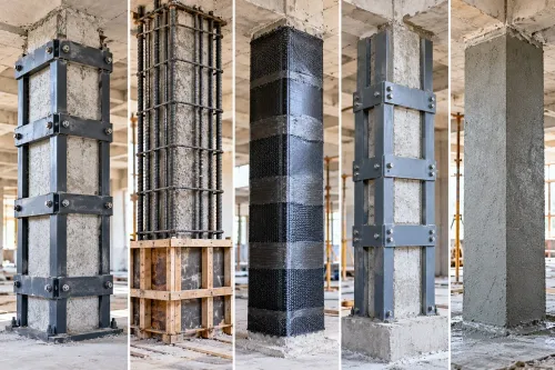
A beam’s failure mode, not the contractor’s preferred material, determines the strengthening system. Match the intervention to the force or deterioration mechanism, then check whether it changes the governing failure from flexure to shear, debonding or brittle compression.
| Failure mode | Appropriate system | Critical limitation |
|---|---|---|
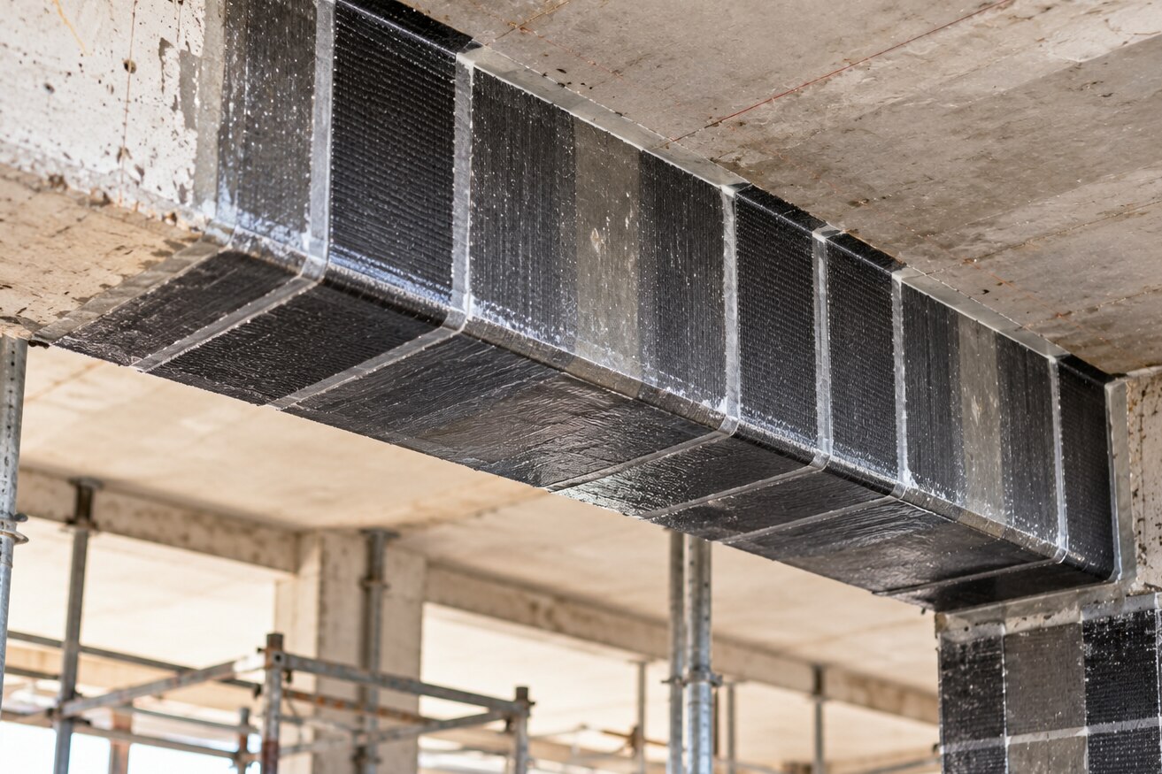
| Flexure | CFRP laminates, steel plates or near-surface-mounted reinforcement in grooves | Check anchorage, concrete-cover bond, ductility and the resulting shear demand; fibre rupture is not the only limit. |
| Shear | Reinforced-concrete jacketing, steel plates or mechanically anchored steel sections; CFRP U-wraps can supplement stirrups | Openings near supports demand a designed load path around cut stirrups or bars. Grout alone does not replace reinforcement. |
| Excessive deflection | CFRP, steel plates or near-surface-mounted reinforcement, selected for added stiffness and tensile capacity | Strengthening after long-term creep does not automatically remove existing deflection. Unload the beam and verify compatibility. |
| Corrosion loss | Reinforced-concrete jacketing with replacement or supplemental reinforcement after removing unsound concrete | Patching spalled cover restores protection, not lost capacity. Assess bar area, bond, stirrups and composite action first. |
| Fire exposure | Reinforced-concrete jacketing or protected steel, designed for the required fire rating | Externally bonded CFRP needs a tested fire-protection system; unprotected resin and fibre can lose performance at elevated temperature. |
| Restricted access | CFRP or near-surface-mounted reinforcement where the substrate can be prepared; thin steel plates where handling and anchorage are feasible | Limited access still requires sound concrete, inspection space and reliable end anchorage. |
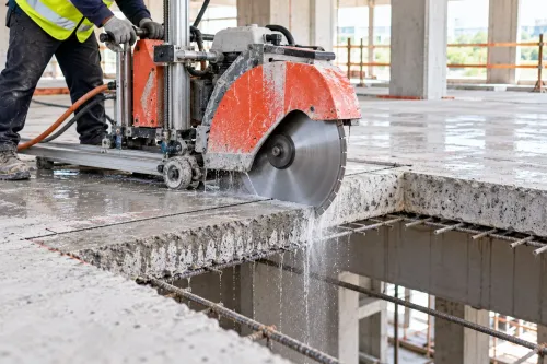
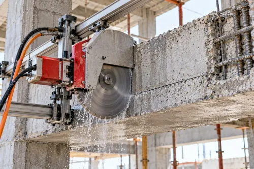
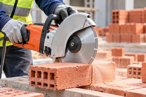
Salasar Demolitions Pvt Ltd can support investigations where a proposed opening or beam cut requires reinforcement locating before any diamond saw work; cutting a stirrup is a structural change, not a minor site adjustment.
Make the intervention effective through sequencing and acceptance checks
Unloading decides how much demand the strengthening will carry. If the beam remains loaded, added steel, concrete or external post-tensioning does not automatically take the dead load; it becomes effective mainly for later loads unless jacking or unloading creates the intended load transfer. Design the temporary works with the strengthening scheme, not as an afterthought.
- Survey the unloaded and loaded conditions, then set out the jacking or propping points shown in the design. Check that supports, slabs and foundations can resist temporary reactions without punching, settlement or local crushing.
- Install temporary propping before removing concrete, cutting reinforcement or drilling anchors. Maintain the specified unload level and record jack pressures and beam movement.
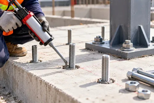
- Prepare the substrate to the specified profile and cleanliness. Inspect reinforcement, anchors, welds, bolts, grout, concrete placement and curing before concealing any connection or interface.
- Transfer load in the specified sequence, remove props gradually, and measure the beam response after each stage. Do not release temporary support until movements and reactions stabilise.
Acceptance requires evidence, not a finished appearance. Compare measured deflection and crack width with the design limits, verify anchor or tendon forces, and confirm the load path into the supports.
Check corrosion sealing, waterproofing and fire protection separately; a beam that passes a strength calculation but fails durability or fire criteria is not an accepted strengthening outcome.
Frequently asked questions
When is beam strengthening required?
Strengthening is required when a verified deficiency prevents the beam from meeting required strength, serviceability, durability or robustness demands.
When should a beam assessment be escalated?
Escalate when inspection finds significant cracking, excessive deflection, corrosion, section loss, uncertain materials, altered loads or evidence of distress beyond a local defect.
What must be verified before strengthening a beam?
Verify existing capacity, actual and future loads, support conditions, reinforcement details, material condition and the complete load path into columns, walls and foundations.
How do you choose a beam strengthening system?
Choose the system according to the governing failure mode, such as flexure, shear, anchorage, corrosion-related section loss or serviceability deflection.
How do you confirm that beam strengthening has worked?
Control the work sequence, prepare and anchor the substrate correctly, follow curing requirements, and record inspections, test results and final acceptance checks.